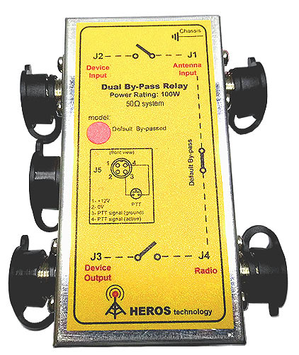
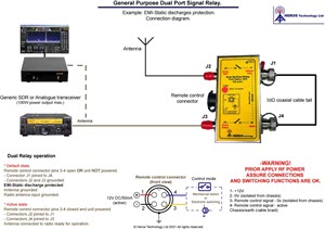
General Purpose Dual Port Signal Relay
100 Watts RF power rating. DC - 1300MHz
| |
|
|
| |
Typical applications include:
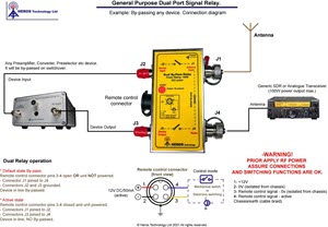
- By-passing a Converter, Preselector, Preamplifier, Filter, etc. device inserted between antenna and a transceiver or transmitter:
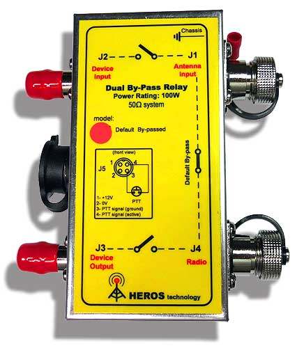
The device is plugged on ports J2 (device input) and J3 (device output). On transmission switchover, via remote control line, the Input and Output RF ports (J2-J3) are by-passed via J1-J4 avoiding being overloaded. Simultaneously ports J2 and J3 are derived to ground adding extra protection.
Other applications let configurations such as: Antenna switching, working with two antennas and one radio, combining two radios and two antennas, protection against electromagnetic pulse (EMP), protection against static discharges (ESD) on stormy weather situations and many more involving RF signal switching. (see below examples)
|
|
| |
|
|
| |
BNC/N connectors version |
|
SO239/SO239 connectors version |
|
|
|
|
N/N connectors version | |
BNC/SO239 connectors version |
| |
|
|
| |
|
|
SO239/N connectors version |
|
SO239/SO239 connectors version |
| |
|
|
Any combination of connectors is possible, please ask. |
| |
General Purpose Dual Port Signal Relay features:
- Default configuration: By-Pass connector J1 to J4. (connectors J2-J3 derived to ground)
- Switching relays: Quad hi-quality telecom RF relays.
- Frequency range: DC - 1300MHz
- Insertion loss: 0.003dB
- Isolation: >100 dB typ.
- Power rating: 100 W max.
- Impedance: 50 Ohm
- Power supply: 11-15 Volts DC/50 mA (Active state). Diode protection.
- Switching time:
- Set:5mS
- Reset: 4mS
- Life expectancy (Mechanical): 20,000,000 operations (at 18,000 operations/hr)
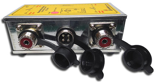
- External Dimensions:
- 55x111x40mm (2.16x4.37x1.57in)
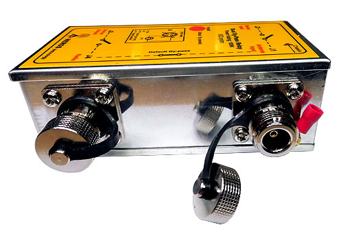
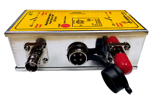
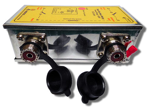
- Connectors: Any combination of BNC, N, SO239 connectors is possible, please ask.
-
Remote Control cable :
Remote control connector type: Foster 4 vias.
RFI-EMI suppression on cable.
Shielded cable type.
|

General Purpose Dual Port Signal Relay
Manual
|
| |
Some application examples (Click on picture to enlarge) |
|
| |
|
|
 |
|
 |
By-passing a device example diagram. |
|
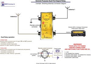
Two antennas One radio example diagram. |
 |
|
 |
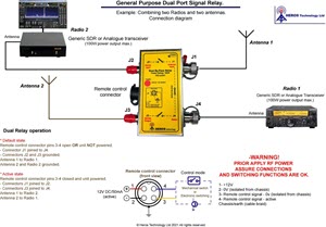
Two antennas Two radios example diagram. |
|
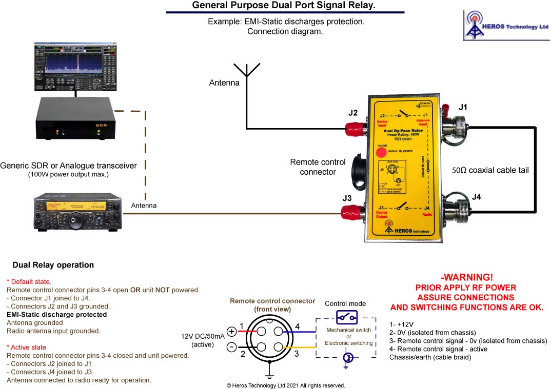
Electrostatic discharge protection (ESD) example diagram . |
| |
|
|
|
| |
|
|
| |
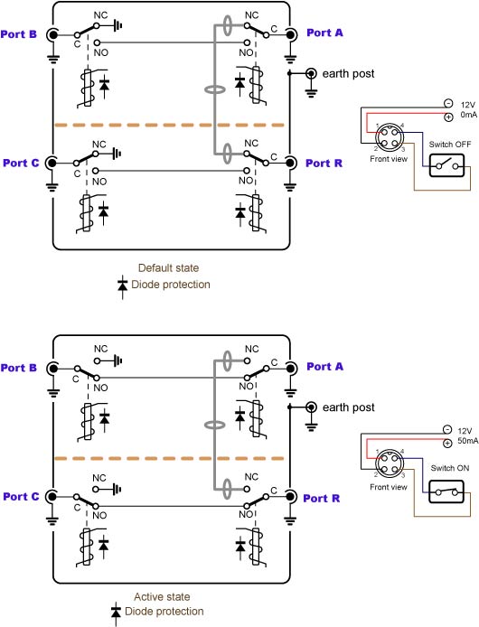
General Purpose Dual Port Signal Relay . How it works. |
|
| |
|
|
 |
|
Default state. (By-passed)
When the General Purpose Dual Port Signal Relay is NOT activated, pins 3 and 4 of the remote control connector are OPEN or the unit is NOT energised Port A and Port R are connected. Port B and Port C are grounded.
Energised state. (NO By-passed)
When the General Purpose Dual Port Signal Relay is energised and pins 3 and 4 of the remote control connector are joined the internal relays switch-over. Port A is connected to Port B and Port C is connected to Port R.. |
|
| |
|
|
|
| |
LF-HF-VHF-UHF General Purpose Dual Port By-Pass Relay options |
|
| |
*Connectors |
Model |
Price |
Order |
|
| |
|
|
|
|
|
| |
BNC / N |
SKU: HS-710N |
£ 305.00 |
 |
|
| |
|
|
|
|
|
| |
BNC / SO-239 |
SKU: HS-710SO |
£ 295.00 |
|
|
| |
|
|
|
|
|
| |
All connectors N type |
SKU: HS-710-x4-N |
£ 315.00 |
|
|
| |
|
|
|
|
|
| |
All connectors SO239 type |
SKU: HS-710-x4-SO239 |
£ 288.00 |
|
|
| |
|
|
|
|
|
| |
All connectors BNC type |
SKU: HS-710-x4-BNC |
£ 278.00 |
|
|
| |
|
Any combination of connectors is possible, please ask. |
|
|
|
| |
All models include:
LF-HF-VHF-UHF Dual Port By-Pass relay, EMI decoupling, shielded remote control cable with connector and user manual in CDROM format |
|
|
|
|
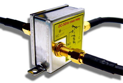
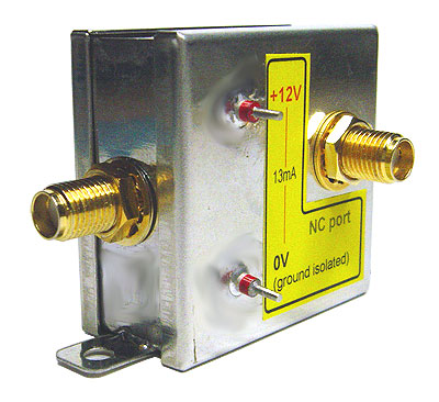
DC-3GHz coaxial relay. Slim size
| |
 |
The DC-3GHz coaxial relay slim size is a remote switchable electromechanical device designed to commute a wide RF spectrum of signals from a common input to either of two outputs (SPDT configuration). Typical applications include: WIFI, cable modems and line cards, CATV, measurement and test equipment, satellite / audio / video tuners, wireless base stations and antennas, RF power stages, etc. |
|
| |
Operation:
- Frequency range: DC to 3GHz.
- Impedance: 50Ω
- Max. switching capacity: 100Watts (HF); 50 W @ 2.5 GHz
- Absolute Max. CW RF power (WSWR 1.2): 65Watts @ 3GHz.
- Activation voltage: 11-15 VDC/14mA standard.
(5VDC and 24VDC voltages available)
- Switch-ON: 5mS.
- Switch-OFF: 6mS.
- Bounce time: 3mS.
Mechanical
- Connectors: SMA
- Dimensions: 37mmx37mmx20mm ( 1.456x1.456x0.787in)
- Weight: 44grams. |
Relay contacts:
- Contact arrangement: SPDT
- Max. switching voltage: 220VDC/250VAC
- Max. switching current: 2 Amp
- Switching endurance: 10,000,000 operations
Insulation
- Dielectric strength:
between open contacts 600Vrms
between contact and coil 1000Vrms
-Surge withstand:
between open contacts 1000Vrms
between contact and coil 1500Vrms |
| |
DC-3GHz coaxial relay. Slim size; SKU: HS-775 |
£ 167.00 |
|
|
|
The set includes:
3GHz slim coaxial relay and user manual in CDROM format. |
|
|
|
| |
Solid State RF Relay. DC-3GHz. Isolation port to port >100dB
No moving parts. No relays |
|
| |
|
|
| |
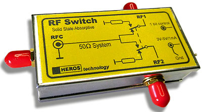 |
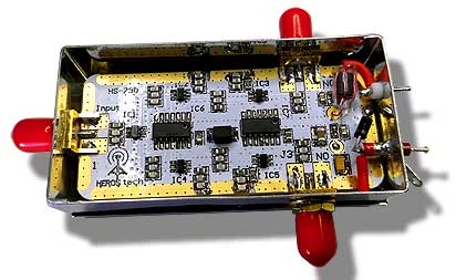
General purpose SPDT solid state RF Relay Absorptive for telecommunication applications. No moving parts, No relays
Our solid state RF Relay do not incorporate any moving parts instead it uses GaAs pHEMT technology switching cells offering low thermal resistance for enhanced mean time between failures (MTBF).
Applications:
- General-purpose medium-power switching in telecommunication applications.
- Switching on 802.11b, g WLAN and Bluetooth systems.
|
|
| |
Solid State Absortive RF Relay manual. Rev03
(January 2021)
|
 |
| |
|
|
|
| |
 |
|
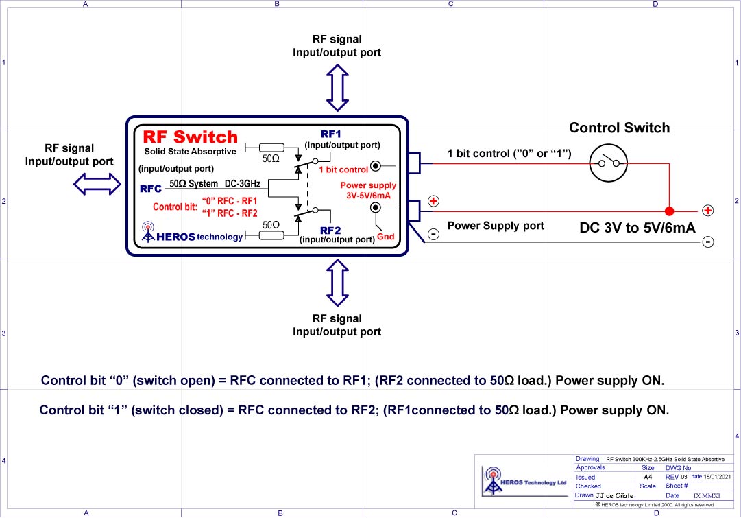
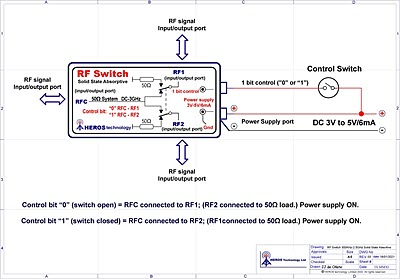
Operating Frequency: DC - 3GHz
Switch Configuration: Form C, SPDT Absorptive.
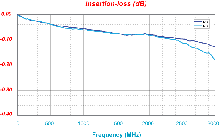
Insertion loss type: 0.3dB @1GHz. ; 0.4dB @3GHz.
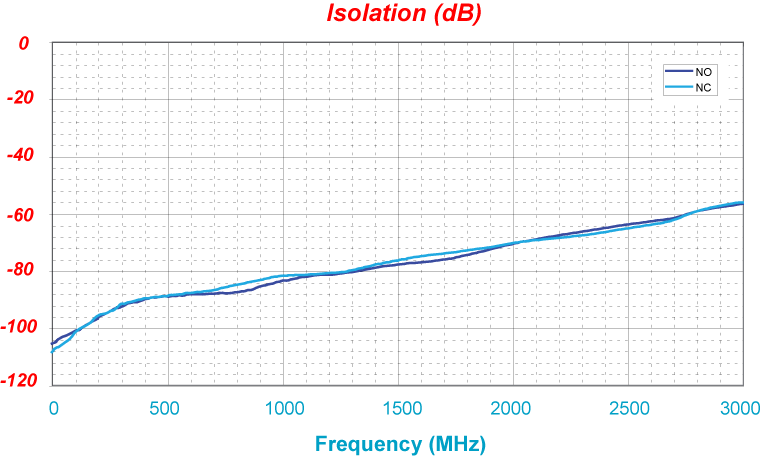
RF1-RF2 port to port Isolation: >100dB
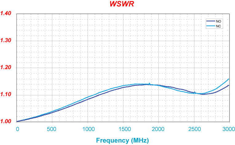
VSWR: 1.2 max.
IP3: 52dBm type
RF power rating absolute max.@ 5VDC:
3 watt(+35dBm) all operating range; 6W(38dBm) @900MHz
Control switching: 1 bit; "0" RFC-RF1; "1" RFC-RF2
Switching time (ON-OFF): 35nS.
Power supply: 3V-5VDC/6mA
Connectors: SMA
Dimensions: 74x37x20mm(2.91x1.45x0.78in) |
|
| |
Connection diagram |
|
|
|
| |
Solid State RF Relay ; SKU: HS-790 |
£ 114.00 |
|
|
| |
The set includes: SPDT solid state RF switch and user manual in CDROM format. |
|
|
|
|
|